I have been using the ARM microcontroller platform for many microcontroller projects in the past years, both the Silicon Labs/Energy Micro EFM32 Controller and the STMicroelectronics STM32. The complexity of setting up these controllers is much greater than previous microcontrollers I have used, Atmel AVR and PIC Micro.
The difficulty comes from all the register settings and combination of these to get the functionality you want in the end. I must say that Energy Micro has had the developer in mind when they made the simplicity studio, where updates and application notes are gathered in the same, easy to use interface. I am sorry to say STMicroelectronics, but your toolchain and documentation have not been anything to speak about. That is, until you made the CubeMX.
CubeMX makes it easy to set up the peripherals and the clock for the microcontroller and generate code for the toolchain of your choice. I have been switching between both ARM Keil, IAR Embedded Workbench and Atollic Truestudio, and I can use the same source code for all of them. Moving or porting code have been very difficult to do in the past as all of the settings would have to be changed, links to libraries would have to be set up again etc. Now a simple click of a button will set up the environment and always be working with the latest updates from ST. If additional peripherals are added to the project I can switch back from the code to CubeMX and add these to the project. Fantastic!
My only complaint is that there is very little documentation of how to set up the peripherals: There are now three documented examples, where of one is blinking a LED, one is to set up reading/writing to a SD card and one is power handling. I don't care about your HAL examples, ST - I want all of them transferred to CubeMX. For all periperhals and variants of setups.
I have now been using about three weeks just to set up my STM32F4-Discovery kit to read and write to a USB memorystick/thumbdrive connected to the USB-micro connector through an USB host adapter. This seems like a simple task, given that there is a HAL example in the repository (User\Repository\STM32Cube_FW_F4_V1.13.0\Projects\STM32F4-Discovery\Applications\FatFs\FatFs_USBDisk). I have been debugging the code and comparing the registers without getting good clues of why the CubeMX setup fail. In the end I found the problem being that the heap and stack size was too small. After doubling these from standard values I finally got the example working with CubeMX.
Here is how I did it:
Start by selecting the STM32F4-Discovery from the Board selection menu:


Now you press the icon "Generate Source code based on user settings" in CubeMX and confirm that you want to open the project.
To be able to copy the functionality of the example from the repository you need to put the code in "usb_host.c" instead of "main.c". This is because the USB settings and state machine is put here.
You want to add the private variables to the user code section 0 of usb_host.c. The #include for fatfs.h is also added to this section in order to prevent changes if future changes in CubeMX is expected:
A custom error handler is added to section 1 where the red LED/LD5 is turned on if any errors occurs:
In the same user section the "MSC_Application" function is added. This is the function that is run after the USB memorystick is set up correctly:
The last thing to add to the "usb_host.c" file is the startup of the "MSC_Application" function from the state machine when the USB stick is ready:
One final thing that is essential to make everything work: There is a bug in the code for the setup of the VBUS for the Discovery board because it is using an external chip (as decribed here). You want to change the settings from SET to RESET in main.c:
Now everything should be working. During debugging I noticed that USBDiskPath variable is not setup correctly if the heap and stack sizes are too small. The variable is not filled with content if the setup of the USB fails. The below picture shows a correct setup:
I hope this post is helping you.. I was struggling getting this to work and got no help from other users on the forums, but pushed through and finally got it running :-)
The difficulty comes from all the register settings and combination of these to get the functionality you want in the end. I must say that Energy Micro has had the developer in mind when they made the simplicity studio, where updates and application notes are gathered in the same, easy to use interface. I am sorry to say STMicroelectronics, but your toolchain and documentation have not been anything to speak about. That is, until you made the CubeMX.
CubeMX makes it easy to set up the peripherals and the clock for the microcontroller and generate code for the toolchain of your choice. I have been switching between both ARM Keil, IAR Embedded Workbench and Atollic Truestudio, and I can use the same source code for all of them. Moving or porting code have been very difficult to do in the past as all of the settings would have to be changed, links to libraries would have to be set up again etc. Now a simple click of a button will set up the environment and always be working with the latest updates from ST. If additional peripherals are added to the project I can switch back from the code to CubeMX and add these to the project. Fantastic!
My only complaint is that there is very little documentation of how to set up the peripherals: There are now three documented examples, where of one is blinking a LED, one is to set up reading/writing to a SD card and one is power handling. I don't care about your HAL examples, ST - I want all of them transferred to CubeMX. For all periperhals and variants of setups.
I have now been using about three weeks just to set up my STM32F4-Discovery kit to read and write to a USB memorystick/thumbdrive connected to the USB-micro connector through an USB host adapter. This seems like a simple task, given that there is a HAL example in the repository (User\Repository\STM32Cube_FW_F4_V1.13.0\Projects\STM32F4-Discovery\Applications\FatFs\FatFs_USBDisk). I have been debugging the code and comparing the registers without getting good clues of why the CubeMX setup fail. In the end I found the problem being that the heap and stack size was too small. After doubling these from standard values I finally got the example working with CubeMX.
Here is how I did it:
Start by selecting the STM32F4-Discovery from the Board selection menu:

The next thing you should do is enable the "RCC-High Speed Clock (HSE)" with the STM32F4-Discovery Crystal, to be able to provide an accurate clock for the USB timing. You cannot continue with the setup for the USB without this enabled.

Next you want to enable "Host_Only" for "USB_OTG_FS". For the STM32F4-Disovery the "Activate_VBUS" should also be selected:
Now you want to Select" Mass Storage Host Class":

...and "USB Disk" from "FATFS" MiddleWares:

Now you want to set up the clock to have HSE and run at 168 MHz, as shown:

Before finishing the settings for the USB you want to set the "Drive_VBUS_FS" to "GPIO_Output" "PC0" under "USB_Host Configuration":

You are now ready to create the code with CubeMX. Select your toolchain (I am using Atollic Truestudio) and Select a proper location for the project and a project name. This is were it is crucial that you use a heap size of 0x400 and a stack size of 0x800. Without this the USB will not work!!

Now you press the icon "Generate Source code based on user settings" in CubeMX and confirm that you want to open the project.
To be able to copy the functionality of the example from the repository you need to put the code in "usb_host.c" instead of "main.c". This is because the USB settings and state machine is put here.
You want to add the private variables to the user code section 0 of usb_host.c. The #include for fatfs.h is also added to this section in order to prevent changes if future changes in CubeMX is expected:
/* USER CODE BEGIN 0 */
//Include the fatfs library here to be inside user code blocks
#include "fatfs.h"
FATFS USBDISKFatFs;           /* File system object for USB disk logical drive */
FIL MyFile;                   /* File object */
char USBDISKPath[4];          /* USB Host logical drive path */
USBH_HandleTypeDef hUSB_Host; /* USB Host handle */
/* USER CODE END 0 */
A custom error handler is added to section 1 where the red LED/LD5 is turned on if any errors occurs:
void USB_Error_Handler(void)
{
  /* USER CODE BEGIN USB_Error_Handler */
  /* User can add his own implementation to report the HAL error return state */
 HAL_GPIO_WritePin(LD5_GPIO_Port,LD5_Pin,GPIO_PIN_SET);
  while(1)
  {
  }
  /* USER CODE END USB_Error_Handler */
}
In the same user section the "MSC_Application" function is added. This is the function that is run after the USB memorystick is set up correctly:
static void MSC_Application(void)
{
  FRESULT res;                                          /* FatFs function common result code */
  uint32_t byteswritten, bytesread;                     /* File write/read counts */
  uint8_t wtext[] = "This is STM32 working with FatFs"; /* File write buffer */
  uint8_t rtext[100];                                   /* File read buffer */

  /* Register the file system object to the FatFs module */
  if(f_mount(&USBDISKFatFs, (TCHAR const*)USBDISKPath, 0) != FR_OK)
  {
    /* FatFs Initialization Error */
    USB_Error_Handler();
  }
  else
  {
      /* Create and Open a new text file object with write access */
      if(f_open(&MyFile, "Even.TXT", FA_CREATE_ALWAYS | FA_WRITE) != FR_OK)
      {
        /* 'STM32.TXT' file Open for write Error */
        USB_Error_Handler();
      }
      else
      {
        /* Write data to the text file */
        res = f_write(&MyFile, wtext, sizeof(wtext), (void *)&byteswritten);

        if((byteswritten == 0) || (res != FR_OK))
        {
          /* 'STM32.TXT' file Write or EOF Error */
          USB_Error_Handler();
        }
        else
        {
          /* Close the open text file */
          f_close(&MyFile);

        /* Open the text file object with read access */
        if(f_open(&MyFile, "Even.TXT", FA_READ) != FR_OK)
        {
          /* 'STM32.TXT' file Open for read Error */
          USB_Error_Handler();
        }
        else
        {
          /* Read data from the text file */
          res = f_read(&MyFile, rtext, sizeof(rtext), (void *)&bytesread);

          if((bytesread == 0) || (res != FR_OK))
          {
            /* 'STM32.TXT' file Read or EOF Error */
            USB_Error_Handler();
          }
          else
          {
            /* Close the open text file */
            f_close(&MyFile);

            /* Compare read data with the expected data */
            if((bytesread != byteswritten))
            {
              /* Read data is different from the expected data */
              USB_Error_Handler();
            }
            else
            {
          /* Success of the demo: no error occurrence */
              //BSP_LED_On(LED4);
              HAL_GPIO_WritePin(LD4_GPIO_Port,LD4_Pin,GPIO_PIN_SET);
            }
          }
        }
      }
    }
  }

  /* Unlink the USB disk I/O driver */
  FATFS_UnLinkDriver(USBDISKPath);
}
The last thing to add to the "usb_host.c" file is the startup of the "MSC_Application" function from the state machine when the USB stick is ready:
static void USBH_UserProcess  (USBH_HandleTypeDef *phost, uint8_t id)
{

  /* USER CODE BEGIN 2 */
  switch(id)
  {
  case HOST_USER_SELECT_CONFIGURATION:
  break;

  case HOST_USER_DISCONNECTION:
  Appli_state = APPLICATION_DISCONNECT;
  break;

  case HOST_USER_CLASS_ACTIVE:
  Appli_state = APPLICATION_READY;
  MSC_Application();
  break;

  case HOST_USER_CONNECTION:
  Appli_state = APPLICATION_START;
  break;

  default:
  break;
  }
  /* USER CODE END 2 */
}
One final thing that is essential to make everything work: There is a bug in the code for the setup of the VBUS for the Discovery board because it is using an external chip (as decribed here). You want to change the settings from SET to RESET in main.c:
  /*Configure GPIO pin Output Level */
  //Bug code: HAL_GPIO_WritePin(OTG_FS_PowerSwitchOn_GPIO_Port, OTG_FS_PowerSwitchOn_Pin, GPIO_PIN_SET);
  HAL_GPIO_WritePin(OTG_FS_PowerSwitchOn_GPIO_Port, OTG_FS_PowerSwitchOn_Pin, GPIO_PIN_RESET);
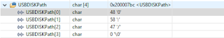
Now everything should be working. During debugging I noticed that USBDiskPath variable is not setup correctly if the heap and stack sizes are too small. The variable is not filled with content if the setup of the USB fails. The below picture shows a correct setup:

I hope this post is helping you.. I was struggling getting this to work and got no help from other users on the forums, but pushed through and finally got it running :-)


